0
0 
November 07, 2022
Insights
Insights
Method Statement For: Windsor Probe Test
Adopted from manufacturer guide & ASTM C803/C803M-18
A. INTRODUCTION
It is proposed that, the in-situ strength will be assessed by performing a penetration resistance test. The test is based on the concept that the depth of penetration of a metal probe fired into the surface depends on the strength of the mortar/grout. A strength determination method based on this approach, using a specially designed bolt and standardized explosive cartridge was developed in USA during the mid-1960’s and is known as Windsor Probe Test. The method is a form of hardness testing and the measurement will relate to the quality of the grout/mortar within the zone of influence of 75mm. The test will be carried out based on method adopted in manufacturer guide & ASTM C803 / C803M – 18.
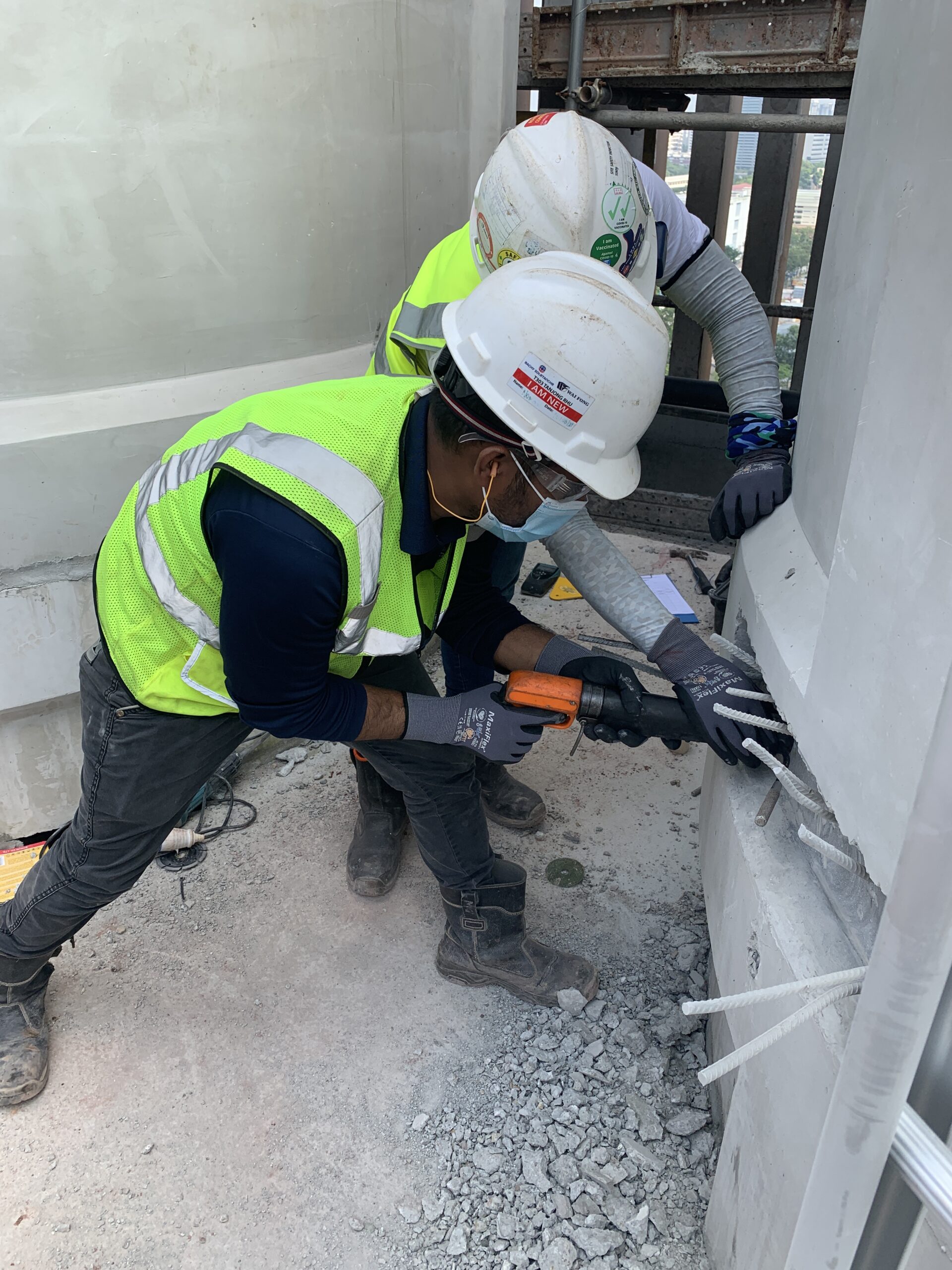
B. TESTING PROCEDURE
1) The test positions should be chosen to minimize the risk of structural cracking or movement of the member under test and should be at least 175mm apart and 100mm from the edge of grout surface. The grout/mortar to be tested must have reached a sufficient degree resistance to penetration so that the probe will not penetrate more than one half the thickness of member thickness and remain firmed embedded.
2) Place the positioning device on the surface of the grout/mortar at the testing location. Mount a probe in the driver unit, position the driver in the positioning device and fire the probe into the grout/mortar while following the safety directions supplied with the apparatus. The probe which is fired into the grout/mortar is of hardened steel alloy. The principle features are a blunt conical end to punch through the matrix near the surface and shoulder to improve adhesion to the compressed grout/mortar and ensure a firm embedment. Three probes, each of 6.35mm in diameter and 79.5mm in length, are fired into the grout/mortar surface using the driver unit.
3) Remove the positioning device and tap the probe on the exposed end with a small hammer to ensure that it has not rebounded and to confirm that it is firmly embedded. Loose probes are rejected.
4) The protruding length of each probe which is firmly held into the grout/mortar are measured relative to the original surface of the grout/mortar by first placing the reference base plate over the probe and position it so that it bears firmly on the surface of the grout/mortar without rocking or other movement. If the grout/mortar has been raised around the base of the probe, remove the crushed grout/mortar to allow the reference base plate to lie flat. If a probe is more than 10 degrees from perpendicular with respect to the surface of the grout/mortar, discard the probe and embed another.
5) The protruding probe length is measured in inches and the mean of three probes is rounded off to the nearest 0.025 inch. The depth of penetration is calculated from this value and the length of the probe.
6) The depth of penetration of a probe can be empirically related to the strength of grout/mortar. The correlation curve to be used is derived based on the Mohs’ No 3 for grout/mortar. Low or Standard Power setting can be used depending on the length of protruding probe. The results corresponding to the power used can be obtained from the Manufacturer’s Chart accordingly. As per Manufacturer’s instruction, the results are obtained from the column MPa Mohs’ No. 3 in the chart attached.
7) If the exposed probe length is less than 31.75mm at low power or more than 62.23mm at standard power, void the test as this method is not suitable for this structure. For mortar/grout testing, preferable to start the test with low power 1st. Change to standard power if the exposed probe length is greater than 59.69mm at low power.
Method of Statement For Ultrasonic Pulse Velocity Test
1.0 Introduction
The velocity of ultrasonic pulses travelling in a solid material depends on the density and elastic properties of that material. The quality of some materials is sometimes related to their elastic stiffness so that measurement of ultrasonic pulse velocity in such materials can often be used to indicate their quality as well as to determine their elastic properties. Material which can be assessed in this way includes concrete.
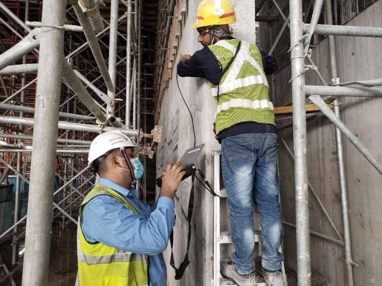
Ultrasonic Pulse Velocity measurements will be carried out in accordance with BS EN 12504-4 : 2021 “Determination of ultrasonic pulses velocity”. The measurement of UPV is carried out by using the equipment called PUNDIT with 54kHz transducers. It works on the production of a pulse of longitudinal vibrations by an electro-acoustical transducer which is held in contact with one surface of the concrete under test. After transversing a known path (L) in the concrete, the pulse vibrations are converted into an electrical signal by the second transducer and the electronic timing circuits change this into a transit time (T) of the pulse measured in micro-seconds. The pulse velocity (V) is given by :- V = L/T
2.0 Choice of Transducer Arrangement
There are three alternative arrangements for the transducers when testing concrete. Whenever possible, the direct
transmission arrangement should be used. This will give maximum sensitivity and provide a well defined path length. It is, however, sometimes required to examine the concrete by using diagonal paths and semi- direct arrangements are suitable for these. 2.1 Indirect transmission In this method, the transmitting transducer is placed on a suitable point on the surface and the receiving transducer is placed on the surface at successive four positions at 100mm apart along a line. The centre to centre distance from the transmitting and receiving transducers is plotted against the transit time. The slope of the straight line obtained by linear regression drawn through these points gives the mean pulse velocity at the surface.
3.0 Applications
The pulse velocity method of testing may be applied to the testing of plain, reinforced and pre-stressed concrete whether it is pre-cast or cast in-situ. The measurement of pulse velocity may be used to determine:
_ the homogeneity of the concrete,
_ the presence of voids, cracks or other imperfections,
_ estimation of crack depth
_ changes in the concrete which may occur with time (i.e. due to the cement hydration) or through the action of fire, frost or chemical attack,
_ the quality of the concrete in relation to specified standard requirements, which generally refer to its strength.
4.0 Correlation of Pulse Velocity and Strength.
Correlation of UPV to concrete strength is affected by several factors which include type of mix proportions, aggregate used, age and moisture content ofconcrete. As the aggregates used in Singapore Concrete Industry is generally consist of granite and natural sand, the main factor which affect the correlation of UPV to concrete strength is mix proportions if the age and moisture content are known. The method of comparison will be used for the testing. UPV measurements will be taken on the affected elements. Similar measurements will be taken on other elements of similar concrete grade as control where concrete strength has met the specified requirements. If the cube strength of the control elements is known, the in-situ strength of the affected elements can be estimated.
5.0 Calibration of UPV Test equipment
The equipment shall be calibrated during the test using the calibration bar prior to commencement of any measurement and after completion of test. Recalibration of equipment is required if there is change of transducers or cables. The procedure of calibration is as follows:
1. Press ZERO/REF cursor as shown in the front panel of the equipment.
2. Apply a suitable couplant to the transducer faces and press them firmly against the calibrated reference bar as provided by the manufacturer.
3. Using the up/down keys adjust the displayed value to that of the calibrated reference
4. When the required value is obtained, press the Zero/Ref switch a second time to store the reference values.